Exploring Virtual And Physical Memory
- 1. Introduction
- 2. Physical Memory
- 3. Virtual Memory
- 4. Memory Paging
- 5. Processes
- 6. Registers
- 7. Virtual Address Structure
- 8. Page Table Translation Process
- 9. References
1. Introduction
In this post we will explore the concepts of virtual and physical memory, memory paging, how processes interact with memory and how the CPU translates virtual addresses to physical.
I am by no means an expert on memory management. However I aim to scratch the surface and hopefully help someone out there grasp these abstract concepts. It is useful to reinforce my own learning as well.
Prerequisites
For the example in the last section where we manually walk the page tables, I’ll be using WinDbg as my debugger of choice. If you wish to follow along, a link can be found below.
Glossary
Here are some frequently used acronyms or terms used throughout the post.
| Frequently Used Term | Description |
|---|---|
| Memory Paging | Refers to the implementation of virtual memory and paging systems. |
| Virtual Memory | An abstracted, logical and linear addressing system in which we manage memory. |
| Physical Memory | The physical memory in which processes are stored. |
| Virtual Page | A single fixed size unit of continous virtual memory. |
| Page Frame | A single fixed size unit of continous physical memory. |
| PFN (Page Frame Number) | Page frame number. The unique identifier for a page frame. |
| Page Fault | An exception raised by the operating system when it attempts to access an invalid page. |
| Process | A running program. |
| Memory Management Unit (MMU) | An integral component of the CPU, responsible for translating and resolving virtual addresses to their corresponding physical address. |
| Page Map Level 4 (PML4) | Page Map Level 4. The top most table used in four level paging. |
| Page Map Level 4 Entry (PML4E) | A table entry within a Page Map Level 4 (PML4) table. |
| Page Directory Pointer Table (PDPT) | Page Directory Pointer Table. The top most table used in three level paging. |
| Page Directory Pointer Entry (PDPE) | A table entry within a Page Directory Pointer Table (PDPT). |
| Page Directory Table (PDT) | Page Directory Table. The top most table used in two level paging. |
| Page Table (PT) | The Page Table contains page table entries that point the virtual page to it’s corresponding page frame. |
| Page Table Entry (PTE) | A table entry within a Page Table (PT). |
| Virtual Random Access Memory (VRAM) | Refers to the virtual memory space. |
| Dynamic Random Access Memory (DRAM) | Refers to the physical memory space. |
| Physical Address Extension (PAE) | An x86 feature that allows for 64 bit page table entries on 32 bit systems. |
2. Physical Memory
Physical memory also known as DRAM (Dynamic Random Access Memory), refers to the physical memory in which programs and information are stored whilst they are actively running.
Physical memory is made up of and measured in what we call page frames, a contiguous section of physical memory.
Page frames are mapped to virtual pages. A single page frame maps to a single virtual page.
Page frames can vary in size.
- 4KB
- 2MB
- 1GB
The default and most common page size is 4KB.
3. Virtual Memory
Virtual memory also know as linear memory is an abstracted way in which memory is managed by modern operating systems.
The concept of virtual memory allows processes to have contiguous memory space, allowing memory management for humans and systems to actually be manageable.
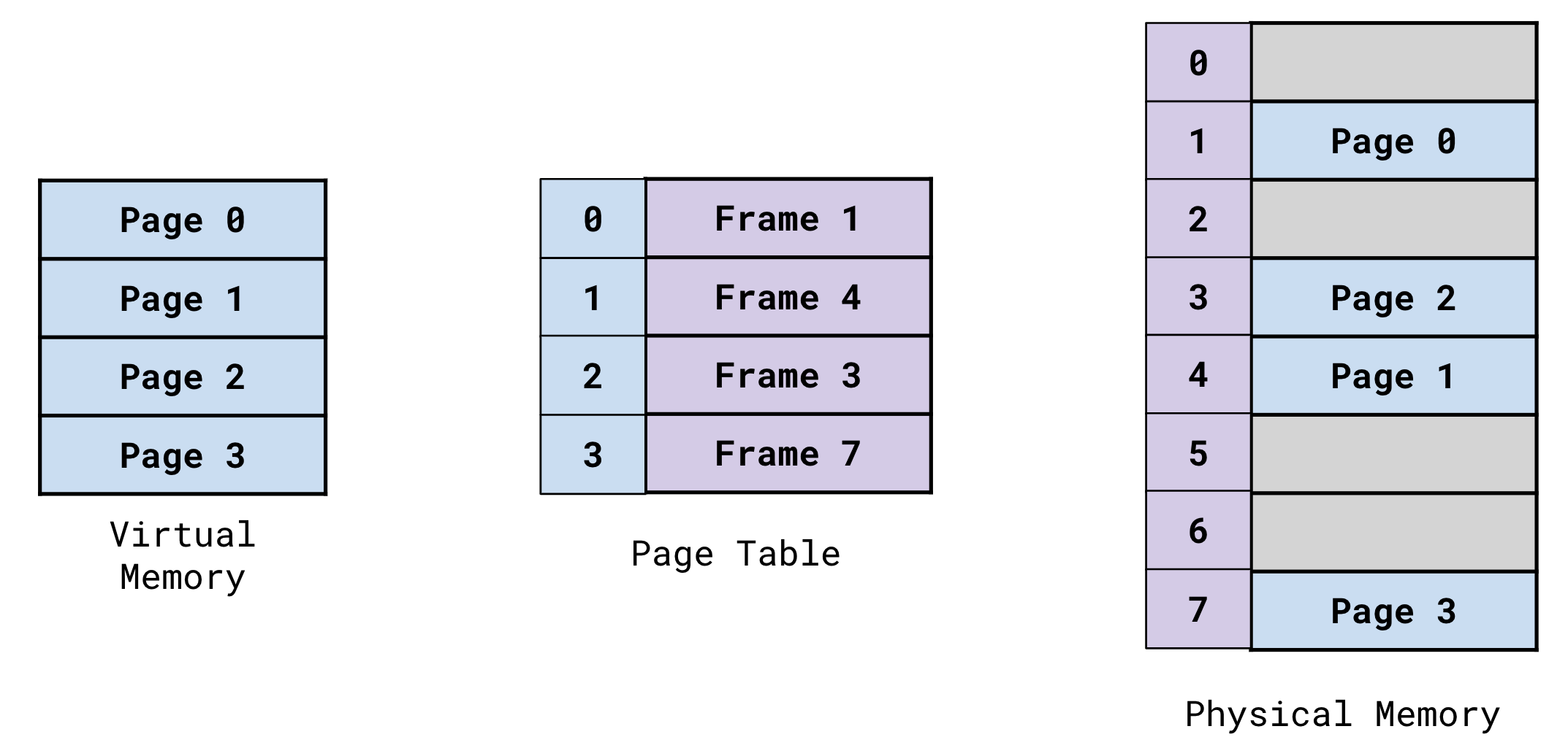
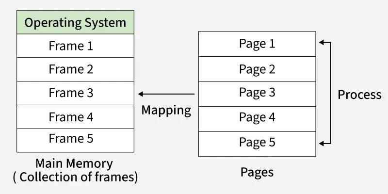
Virtual memory is organized and structured in virtual memory pages. These virtual pages are dynamically mapped to page frames within physical memory. Virtual pages can vary in size (4KB, 2MB, 1GB) however are typically 4KB in size.
Each processes’ page map is responsible for mapping these virtual pages to physical page frames.
Virtual memory is translated to it’s corresponding location in physical memory by the Memory Management Unit (MMU) of the CPU. This is done by an important process refered to as ‘page walking’ or a page table lookup.
We will go into further detail about page walking, paging systems and virtual memory in the next section.
Why Use Virtual Memory?
The implementation of virtual memory, allows processes to have their own independent and isolated space within the virtual memory space, preventing processes’ instructions from overlapping with one another.
Let’s say that there are two programs running. Both programs have their preferred base address at 0x7FFFFFFFFFFF.
They would both have completely isolated memory spaces.
For example, what’s stored at 0x7F793950000 in Process1, is different to what’s stored at 0x7F793950000 in Process2.
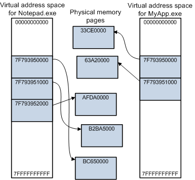
This is because the mapping of the virtual addresses in each process point to different locations in physical memory.
Each program has it’s own isolated section of memory with sequential addressing, this is much more logical and convenient to work with.
It provides us with an abstracted way to work with memory in which our addressing scheme is sequential and logical.
We know that the instructions of our programs will be mapped sequentially within a specific memory address range, not having to work with it’s instructions scattered all over the place in physical memory.
Imagine before the days of high level languages and the abstraction of virtual memory. You would be programming in Assembly and your programs instructions would be fragmentally mapped all over memory! They still are now… however now we don’t have to see or worry about that due to the implementation of virtual memory!
So nowadays, we reap the benefits of this sequential addressing and we let the Operating System and Memory Management Unit (MMU) of the CPU handle the abstraction of finding out where our instructions actually live in our physical memory (DRAM).
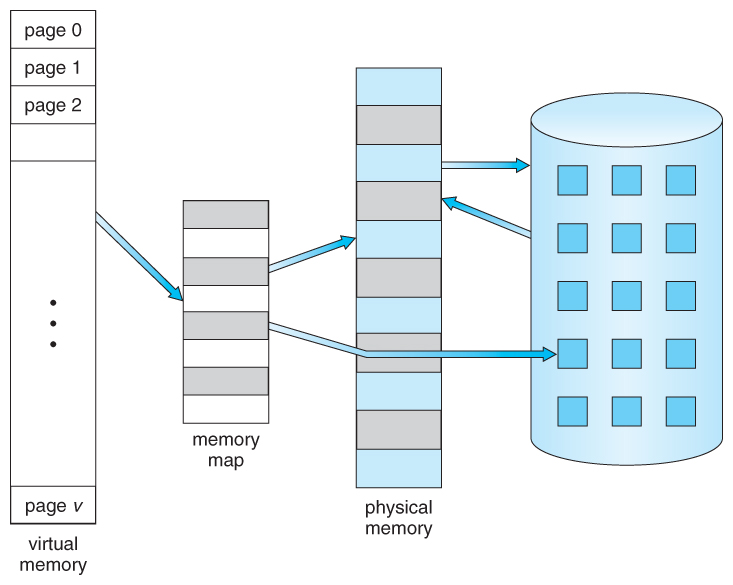
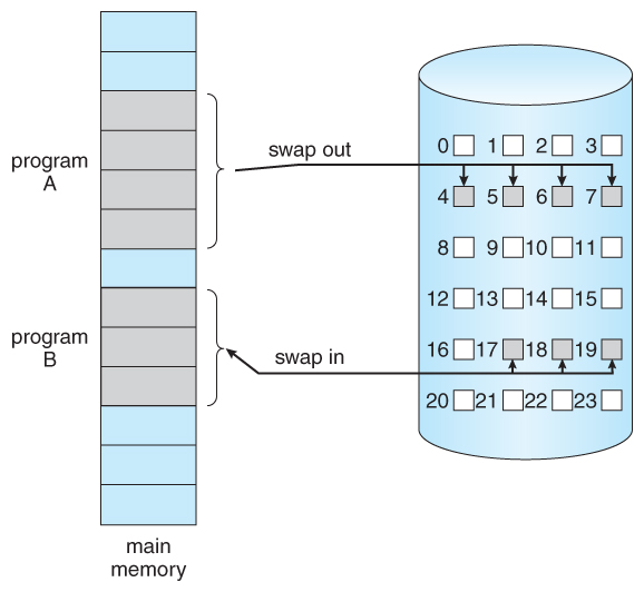
The use of virtual memory allows programs to use more memory than is physically available. The operating system helps to facilitate this by dynamically swapping out virtual pages to and from disk storage when needed.
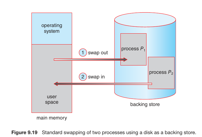
This means the operating system can just prioritize and keep track of a pages’ activity levels. It can also swap out pages when the running process needs it, swapping the needed virtual page from disk storage for an inactive one currently mapped in RAM.
Despite being at maximum DRAM capacity, programs can continue to be run. As the operating system triggers page faults and swaps out inactive pages currently mapped in physical memory (DRAM) for the required virtual pages from disk storage.
The act of swapping out these virtual pages allows the operating system to run more programs concurrently.
More information on demand paging can be found here.
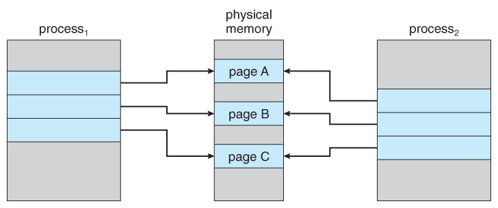
The abstraction of virtual memory also improves resource optimization. An example of this is lets say that Windows is running two ‘mspaint.exe’ processes. The mspaint.exe program, requires the User32.dll library.
The operating system can map this dependency into physical memory once, and have the page map of each mspaint.exe process, pointing to the same area in physical memory. Saving precious resources, by not having to map the library multiple times.
Memory paging and specifically the ability to dynamically swap out pages from RAM to disk storage, greatly improves resource optimization.
A process can have its already executed instructions and the virtual pages they live on, swapped to disk if inactive. In turn freeing up physical memory for another program to use.
As you can see, there are many benefits to this abstraction.
- Sequential, linear and logical addressing scheme.
- Isolated and protected memory space for each running program.
- Measureable and mutually agreed upon units of memory.
- Improved memory management, now being much more efficient.
- Resource optimization.
4. Memory Paging
Memory paging refers to the implementation and use of virtual memory.
Paging protocols and systems allow your hardware and operating system to handle the abstraction of virtual memory and make modern memory management possible.
As we touched on briefly in the previous section, the use of paging allows your operating system to provide each process with it’s own contingious memory space (or so it thinks).
Memory paging also allows your processes to have their own isolated memory space, preventing their instructions from overlapping with one another.
Alongside this, your operating system also provides each process with a page map, the page map being responsible for mapping the processes virtual pages to physical page frames.
We break down memory into measureable, useable and contingious fixed size units. We then have systems and processes in place to:
- Map virtual units of memory to physical units of memory.
- Through the use of bit flagging, apply properties and permissions to these contingious fixed size units of memory.
- Analyze and swap virtual memory pages back and fourth between disk storage and RAM.
- Prioritise which virtual pages to swap out, swapping inactive pages for pages in demand.
- Resolve the mapping of virtual pages to their corresponding physical page frames.
- Handle and resolve when the operating system attempts to access an invalid page.
Memory paging has made modern computers what they are today.
How Is Memory Measured?
Here we will reiterate and elaborate from the earlier sections regarding virtual pages and physical page frames.
Physical Memory
Physical memory consists of page frames. These are a continous section of physical memory in which virtual pages are mapped too.
Page frames can be identified by their Page Frame Number (PFN), this is the unique identifier for a page frame. The PFN is the physical base and/or start address of the page frame.
Virtual Memory
Virtual memory consists of virtual pages. These are a continous section of virtual memory which map to physical page frames.
Page frames are the same size as virtual memory pages, a single virtual page is mapped to a single page frame.
Pages can be one of multiple sizes.
- 4KB
- 2MB
- 1GB
The default and most common page size is 4KB.
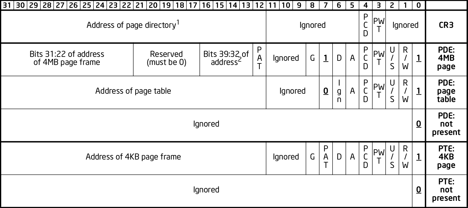
Page Table Entry (PTE) Structure
The image below shows the breakdown of a 64 bit page table entry (PTE).
The notable encoded flags are.
| Bit Range | Flag | Description |
|---|---|---|
| 51:12 | Page Frame Number (PFN) | The page frame number of the frame that the virtual page is mapped too. |
| 0 | Present | The present flag is used to set the status of whether the page is mapped in physical memory or not. If set to 1, the page is mapped, if set to 0, the page is not mapped in memory. |
| 1 | Read/Write | The Read/Write flag determines the pages read and write permissions. If set to 1, the page is both read and write. If set to 0, read only. |
| 2 | User/Supervisor | The User/Supervisor flag determines if the page can be accessed from both usermode and the kernel, or just from the kernel. If set to 1, the page can be accessed by UM and KM. If set to 0 and only KM. |
| 5 | Accessed | The Access flag stores the state of whether the page has been accessed recently. If set to 1 means it has been accessed. If set to 0 means the page has not been accessed since the bit was last cleared/zeroed. |
As you can see bits (51:12) are responsible for the page frame number (PFN). If you’re on 32 bit with PAE disabled, then it’s bits (31:12). Bits (11:0) are always encoded flags.
Page Table Entries (PTE) contain a PFN that identifies which page frame the virtual page containing the instruction is mapped too.
The Operating System and Memory Management Unit (MMU) of the CPU use the PFN along with the page offset to calculate the physical memory address and determine the location of the instruction within the page.
As virtual pages are dynamically swapped in and out of disk memory, page table entries (PTE) are updated with the new page frame number.
It is important to note, Page Table Entries (PTE) change from 32 bit to 64 bit in size when PAE is enabled.
Fetch, Decode, Execute Cycle
Your CPU consists of multiple parts, one of those parts being the Memory Management Unit (MMU). The MMU is responsible for translating virtual addresses to their corresponding physical location in memory.
In each iteration of the fetch, decode and execute cycle of the CPU. The CPU will perform a check inside of it’s cached buffer, the TLB (Translation Lookaside Buffer). This is to see if the virtual memory address has already been translated.
In the event that the virtual address has not been translated and is not stored within the TLB buffer, this is called a TLB MISS. The MMU will then have to perform a page table lookup in order to determine the physical address. After translation, the MMU will then cache it in the TLB buffer to help with future lookups.
The MMU of the CPU traverses through the page tables until it calculates and reaches the physical location of the virtual memory address.
The Control Unit of the CPU then fetches the instruction using the physical address of where it lives in physical memory (DRAM). It then passes the instruction to the Arithmetic Logic Unit (ALU) of the CPU to execute.
If you would like to learn more about this, feel free to view my post here, that covers the Von Neuman architecture and the fetch, decode and execute cycle.
An exmaple of the page table lookup can be found in the last section of this post.
Demand Paging
Demand paging refers to the idea of dynamically mapping virtual pages to physical page frames, as they are needed.
Virtual pages are NOT loaded into memory until needed at the point of instruction execution.
Only a subset of each processes’ virtual pages are mapped into RAM at a given time. With ideally storing the majority of virtual pages of a process, in disk storage.
Lets take the Calculator program as an example.
We run it and the initial pages responsible for loading the UI and initial functionality are swapped from disk and mapped into memory.
However, I might not click the button responsible for subtraction until I need to subtract two numbers. The virtual page that stores the function definition used by the subtraction button, does NOT need be mapped until the function is called.
When the subtraction button is clicked, the instruction pointer of the CPU jumps to the function definition responsible for subtracting two numbers.
The operating system then raises a page fault as the virtual page is not available in memory. The virtual page is then swapped from disk and mapped to an available page frame.
The key takeaway here is:
A programs initial instructions and their pages are mapped into memory. And through the use of page faults, only WHEN the program requires the virtual page, is it then fetched and swapped from disk storage.
As you can see, the use of demand paging, swapping virtual pages to and from disk, has allowed us to utilze and manage memory much more efficiently.
Page Faults
A page fault is an exception that occurs when the operating system attempts to access an invalid page.
An invalid page is a page that is:
- A page that is not located in RAM at the time of the virtual page being accessed.
- Marked as invalid.
During this translation process the operating system attempts to access the virtual page, when it cannot, a page fault exception is raised and the programs’ execuction is halted.
Your operating system determines and swaps pages that haven’t been ‘active’ or have had their instructions executed recently, to disk. This is to save precious memory resources.
Page faults occur when the the Memory Management Unit (MMU) of the CPU is translating an address from virtual to physical.
During the translation process, the operating system attempts to access the virtual page the virtual address in question lives within. If the page is an invalid page, a page fault occurs.
A page fault generally occurs in these circumstances.
- When an inactive virtual page of a process was swapped back to disk to save resources.
- The necessary page (library dependency, etc…) to continue program execution isn’t currently mapped in RAM.
- For unknown reason, the bits that determine page validity might be set to invalid for the virtual page you’re trying to access.
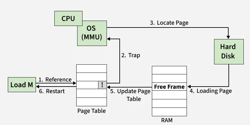
This page fault is handled in sequence by the following steps.
- The operating system attempts to access an invalid page, a page fault occurs.
- The page fault handler is invoked. The programs’ execution is halted.
- The operating system determines which page is needed. (Missing library, missing pages of the executable itself, etc…).
- The page is searched for and once found, it is read/copied by the operating system.
- The operating system maps the virtual page to an available page frame. In the event there are no page frames are available, an existing page will be evicted from its page frame, and the new page is mapped.
- The Page Table Entry (PTE) for that page, is updated with the new page frame number.
- The exception has been handled. The program continues to execute instructions at the instruction pointer where it left off.
Paging Levels
In this section we will cover the following.
- Physical Address Extension (PAE).
- Two Level Paging.
- Three Level Paging.
- Four Level Paging.
- Page Table Entry (PTE) Structure.
We have to quickly talk a little about Physical Address Extension (PAE).
What is it? Why do I need to care? How does it impact memory paging?
I’m going to mention it quite a bit throughout the paging section of this post, I figured I would give the explanation first.
Physical Address Extension (PAE) is a feature of the x86 architecture brought in by Intel to solve the issue of being unable to utilize more than 4GB of physical memory at once.
This is not so much an issue anymore, but back in the day before the transition to 64 bit, if you were running a 32 bit system, you could not utilize more than 4GB of physical memory at a given time.
Why? This is because two level paging uses 32 bit addresses. Each entry within the page tables are 32 bit or 4 bytes in size.
As you can see, the page frame address is at bits (32:11) and bits (11:0) are encoded flags.
By only having 20 bits per entry allocated for storing the page frame number, this sets a hard limit on the maximum page frame numbers we can use.
2^20 * 4KB = 4GB of physical memory
However enabling Physical Address Extension (PAE) on a 32 bit system does a few notable things.
- Extends two level paging to three level paging by adding another table to the page map.
- Extends 32 bit physical addresses to 36 bit physical addresses, virtual addresses stay as 32 bit.
- Extends page table entries from 32 bit (4 bytes) to 64 bit (8 bytes) each.
- Breaks through the fixed limitation barrier of storing large page frame numbers in page table entries.
- Page table entries can store a page frame number from bits (51:12), previously from bits (31:12) without PAE enabled.
The extension of page table entry (PTE) size from 32 bit to 64 bit, allows for a change in the amount of bits allocated for the page frame number. Previously the bit range allocated was (31:12), with PAE enabled, this changes to bits (51:12).
This makes for a 20 bit increase. With 40 bits now allocated for the PFN part of the PTE, this allowed for larger page frame numbers to be referenced and used within page table entries.
In turn, this allowed previously unaddressed page frames, to be referenced and mapped with the eagerly awaiting virtual memory pages. Allowing us to be able to utilize more than the previous 4GB DRAM limit that occurs with using 32 bit sized page table entries.
Nowadays nearly everyone uses 64 bit systems with four level paging, however it’s important to know about PAE.
Two Level Paging
Two level paging is the default paging system used in 32 bit systems.
Although three level paging is typically the most commonly used paging system by those using 32 bit (x86) systems. This is because enabling Physical Address Extension (PAE) in x86 enables the use of 64 bit page table entries.
This in turn allows one to utilize more than 4GB of physical memory.
Who wouldn’t want to get the most out of their hardware? Yet again, not many people are using 32 bit systems nowadays.
Two level paging consists of two page tables.
- Page Directory Table (PDT)
- Page Table (PT)
Enabling Physical Address Extension (PAE) adds a third table to the page map, making it three level paging.
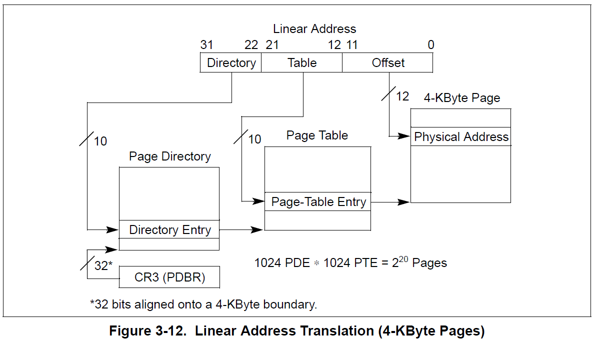
Two level paging on 32 bit systems, uses the 32 bit virtual address structure seen below.
| Table Index | Bit Range | Description |
|---|---|---|
| Page Directory Table Index | 31:22 | The index of the entry within the PDT. |
| Page Table Index | 21:12 | The index of the entry within the PT. |
| Page Offset | 11:0 | The offset between the exact location within a page and the page frame base. |
The CR3 register always stores the physical address of the top most table in the table hierarchy. In the case of two level paging, the CR3 holds the physical base address of the Page Directory Table (PDT).
Each entry within the tables are pointers. They store an encoded value that contains the physical base address of the next table in the two table hierarchy. Specifically bits (12:31) of the addresses pointed to.
Let’s take a look at the structure for the table entries.
As you can see, bits (12:31) are the bits representing the physical address of the next table in the hierarchy. In this case, bits (12:31) of the value stored at the Page Directory Entry (PDE) address would give us the physical base address of the Page Table (PT).
The Page Table Entry (PTE) contains information such as the page frame number (PFN) and encoded flags. This page frame is the frame that is mapped to the virtual page to be translated.
Remember…
When PAE is enabled on 32 bit systems, two level paging receives an additional table in the hierarchy, going from two level paging to three level paging.
Three Level Paging
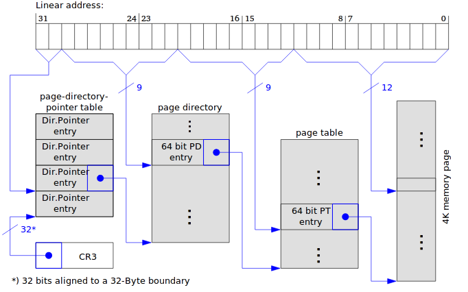
Three level paging consists of three page tables.
- Page Directory Pointer Table (PDPT)
- Page Directory Table (PDT)
- Page Table (PT)
Three level paging can be used by both 32 bit and 64 bit systems.
Three level paging on 32 bit systems use the 32 bit virtual address structure seen below.
| Table Index | Bit Range | Description |
|---|---|---|
| Page Directory Table Index | 31:22 | The index of the entry within the PDT. |
| Page Table Index | 21:12 | The index of the entry within the PT. |
| Page Offset | 11:0 | The offset between the exact location within a page and the page frame base. |
Three level paging on 64 bit systems use the 48 bit virtual address structure seen below.
| Bit Range | Field | Size | Description |
|---|---|---|---|
| 63:48 | Sign Extend | 16 bits | Reserved unused bits. |
| 47:39 | PML4 Offset | 9 bits | Contains the index of the entry in the PML4 table. |
| 38:30 | PDPT Offset | 9 bits | Contains the index of the entry in the page directory pointer table. |
| 29:21 | PDT Offset | 9 bits | Contains the index of the entry in the page directory table. |
| 20:12 | PT Offset | 9 bits | Contains the index of the entry in the page table. |
| 11:0 | Page Offset | 9 bits | The offset between the exact location within a page and the page frame base. |
Further infromation about the virtual memory address structure can be found here.
Physical Address Extension (PAE) needs to be enabled in order to use three level paging on 32 bit systems.
The below paragraph is copied/pasted between the 2/3/4 level paging sections as it applies to all three paging systems.
Each entry within the tables are pointers. They store an encoded value that contains the physical base address of the next table in the three table hierarchy. Specifically bits (12:51) of the addresses pointed to.
- The Page Directory Pointer Entry (PDPE), points to the base of the Page Directory Table (PDT).
- The Page Directory Entry (PDE) points to the base of the Page Table (PT).
- The Page Table Entry (PTE) points to the base of the page frame.
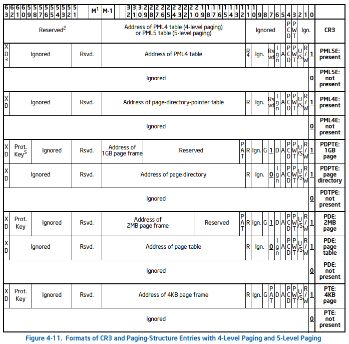
Let’s take a look at the structure for 64 bit table entries.
As you can see, bits (12:51) are the bits representing the physical address of the next table in the hierarchy.
In this case, bits (12:51) of the value stored at the Page Directory Pointer Entry (PDPE) address would give us the physical base address of the Page Directory Table (PDT).
The acronyms for each table entry are typically as so.
- Page Directory Pointer Entry (PDPE)
- Page Directory Entry (PDE)
- Page Table Entry (PTE)
The CR3 register always stores the physical address of the top most table in the table hierarchy. In the case of three level paging, the CR3 holds the physical base address of the Page Directory Pointer Table (PDPT).
Four Level Paging
Four level paging is used in 64 bit systems.
It is the most commonly used paging system.
Four level paging uses 48 bit virtual memory addressing.
| Bit Range | Field | Size | Description |
|---|---|---|---|
| 63:48 | Sign Extend | 16 bits | Reserved unused bits. |
| 47:39 | PML4 Offset | 9 bits | Contains the index of the entry in the PML4 table. |
| 38:30 | PDPT Offset | 9 bits | Contains the index of the entry in the page directory pointer table. |
| 29:21 | PDT Offset | 9 bits | Contains the index of the entry in the page directory table. |
| 20:12 | PT Offset | 9 bits | Contains the index of the entry in the page table. |
| 11:0 | Page Offset | 9 bits | The offset between the exact location within a page and the page frame base. |
Further infromation about the virtual memory structure can be found here.
Four level paging consists of four page tables.
- Page Map Level 4 (PML4)
- Page Directory Pointer Table (PDPT)
- Page Directory Table (PDT)
- Page Table (PT)
Each entry within the tables are pointers. They store an encoded value that contains the physical base address of the next table in the four table hierarchy. Specifically bits (12:51) of the addresses pointed to.
- The Page Map Level 4 Entry (PML4E), points to the base of the Page Directory Pointer Table (PDPT).
- The Page Directory Pointer Entry (PDPE), points to the base of the Page Directory Table (PDT).
- The Page Directory Entry (PDE) points to the base of the Page Table (PT).
- The Page Table Entry (PTE) points to the base of the page frame.
Let’s take a look at the structure for the 64 bit page table entries.
As you can see, bits (12:51) are the bits representing the physical address of the next table in the hierarchy.
In this case, bits (12:51) of the value stored at the Page Map Level 4 Entry (PML4E) address would give us the physical base address of the Page Directory Pointer Table (PDPT).
The acronyms for each table entry are typically as so.
- Page Map Level 4 Entry (PML4E)
- Page Directory Pointer Entry (PDPE)
- Page Directory Entry (PDE)
- Page Table Entry (PTE)
The CR3 register always stores the physical address of the top most table in the table hierarchy. In the case of four level paging, the CR3 register holds the physical base address of the Page Map Level 4 Table (PML4).
I go through an example here at the end of this post to demonstrate how the CPU walks the page tables using four level paging.
5. Processes
A process is simply a running program. When you run an executable on Windows, the kernel will initialize an _EPROCESS type.
As aforementioned, the kernel will provide this process with it’s own virtual memory address space, along with a page map. The page map, provides the mapping of virtual pages to their corresponding physical page frames.
Let’s take a look into the process structure for Windows.
struct _EPROCESS
{
    struct _KPROCESS Pcb;                                //0x0
    struct _EX_PUSH_LOCK ProcessLock;                    //0x1c8
    VOID* UniqueProcessId;                               //0x1d0
    struct _LIST_ENTRY ActiveProcessLinks;               //0x1d8
    struct _EX_RUNDOWN_REF RundownProtect;               //0x1e8
}
When you run a program, the Windows kernel initializes an EPROCESS type. This EPROCESS type has a child structure named KPROCESS.
struct _KPROCESS
{
    struct _DISPATCHER_HEADER Header;                    //0x0
    struct _LIST_ENTRY ProfileListHead;                  //0x18
    ULONGLONG DirectoryTableBase;                        //0x28
    struct _LIST_ENTRY ThreadListHead;                   //0x30
    ULONG ProcessLock;                                   //0x40
    ULONG ProcessTimerDelay;                             //0x44
    ULONGLONG DeepFreezeStartTime;                       //0x48
    struct _KAFFINITY_EX* Affinity;                      //0x50
    struct _KAB_UM_PROCESS_CONTEXT AutoBoostState        //0x58
    struct _LIST_ENTRY ReadyListHead;                    //0x68
    struct _SINGLE_LIST_ENTRY SwapListEntry;             //0x78
    struct _KAFFINITY_EX* ActiveProcessors;              //0x80
}
The KPROCESS structure contains a ULONGLONG type named DirectoryTableBase, we are going to circle back to this in a minute to explain why this variable is crucial to the page translation process.
For now, simply put, the DirectoryTableBase value contains the physical base memory address of the top most page table within the page map. Using four level paging, this would be the Page Map Level 4 (PML4) table.
This is the key address needed for the Memory Management Unit (MMU) to begin walking the page tables.
As previously mentioned, each process when initialized by the kernel, is provided it’s own page map.
The Memory Management Unit (MMU) of the CPU can walk through the tables within the processes’ page map to perform the necessary translation from the virtual address to it’s corresponding physical location in physical memory (DRAM).
Process Context Switching
- Work in progress…
6. Registers
Registers are an integral and core component of the CPU. Some are general purpose, some have specific purposes. They are an area in which the CPU can store data/information that can be accessed immediately as opposed to Dynamic Random Access Memory (DRAM).
I won’t go into detail on this, but I will explain the registers that are important in the context of this post.
CR0 - Control Register 0
The CR0 is a 32 bit register that is encoded with information around various flags.
| Bit | Name | Description | ||
|---|---|---|---|---|
| 0 | PE (Protection Enable) | When PE = 1, the processor operates in protected mode. When PE = 0, it operates in real mode. | ||
| 2 | EM (Emulation) | When EM = 1, the processor uses emulation for coprocessor instructions (e.g., FPU instructions). | ||
| 3 | TS (Task Switched) | When TS = 1, the task switch has occurred and the task state is stored. | ||
| 4 | ET (Extension Type) | This bit determines the type of the processor. In modern processors, it is usually 0 (x86). | 0 | |
| 8 | WP (Write Protect) | When WP = 1, it causes write-protected pages to raise exceptions when written to by user-level code. | ||
| 13 | PG (Paging Enable) | When PG = 1, it enables paging and the virtual-to-physical address translation takes place. | ||
| 14-31 | Reserved | Reserved bits, must always be 0. |
The important notable flags are:
- PG (Bit 13). This enables or disables the use of memory paging.
The CR3 register stores the physical base address of the top most page table in the table hierarchies.
- PML4 in four level paging.
- PDPT in three level paging.
- PDT in two level paging.
As we just touched on process context switching, it’s important to know that the kernel updates the CR3 register as one changes process contexts. When you switch process, the CR3 is updated to point to the top most table of the active processes page map.
In the event of a TLB miss during the fetch, decode and execute cycle of the CPU. The CPU will perform a page table lookup. Fetching the physical base address of the top most table in the page map, from the CR3 register in order to begin the translation.
CR4 - Control Register 4
The CR4 is a 32 bit register that is encoded with informatioun around various flags.
| Bit | Name | Description |
| 0 | VME (Virtual Mode Extension) | Enables the Virtual 8086 mode extensions. This allows applications to run in virtual 8086 mode (real mode under a protected environment) for certain legacy programs. |
| 1 | PVI (Protected-Mode Virtual Interrupts) | When PVI = 1, the processor checks the state of the interrupt flag during protected mode interrupt handling, allowing virtual interrupt handling in protected mode. |
| 3 | DE (Debugging Extensions) | When DE = 1, the processor enables hardware debugging features like single-step and breakpoint support. |
| 4 | PSE (Page Size Extensions) | When PSE = 1, it enables the use of 4MB page sizes in 32-bit mode, instead of the default 4KB pages. This is useful for large applications. |
| 5 | PAE (Physical Address Extension) | When PAE = 1, Physical Address Extensions are enabled, allowing the CPU to access more than 4GB of physical memory (up to 64GB) in a 32-bit system. |
The important notable flags are:
- Physical Address Extension (Bit 5), is responsible for enabling/disabling Physical Address Extension.
- Page Size Extensions (Bit 4), is responsible for enabling/disabling the use of 4MB virtual pages.
7. Virtual Address Structure
A virtual memory address when broken down, is simply a series of indexes, the index referring to the entry number within the tables.
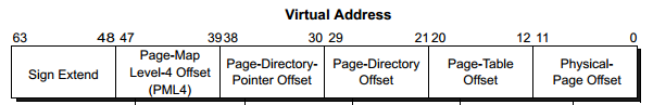
The structure of a 64 bit virtual address is as followed.
| Bit Range | Field | Size | Description |
|---|---|---|---|
| 63:48 | Sign Extend | 16 bits | Reserved unused bits. |
| 47:39 | PML4 Offset | 9 bits | Contains the index of the entry in the PML4 table. |
| 38:30 | PDPT Offset | 9 bits | Contains the index of the entry in the page directory pointer table. |
| 29:21 | PDT Offset | 9 bits | Contains the index of the entry in the page directory table. |
| 20:12 | PT Offset | 9 bits | Contains the index of the entry in the page table. |
| 11:0 | Page Offset | 9 bits | The offset between the exact location within a page and the page frame base. |
As aforementioned in the previous sections, four level paging is used in 64 bit systems. Four level paging uses a 48 bit virtual address structure. The top 16 sign extend bits of a 64 bit virtual address are not used.
0x7FF7051FF9B4
Let’s take the following 64 bit address as an example and lets break down the fields to calculate our indices, these indexes will allow us to locate the necessary page table entries, which in turn, will allow us to traverse through the page table hierarchy.
First we convert our virtual memory address from hexadecimal to binary.
0111 1111 1111 0111 0000 0101 0001 1111 1111 1001 1011 0100
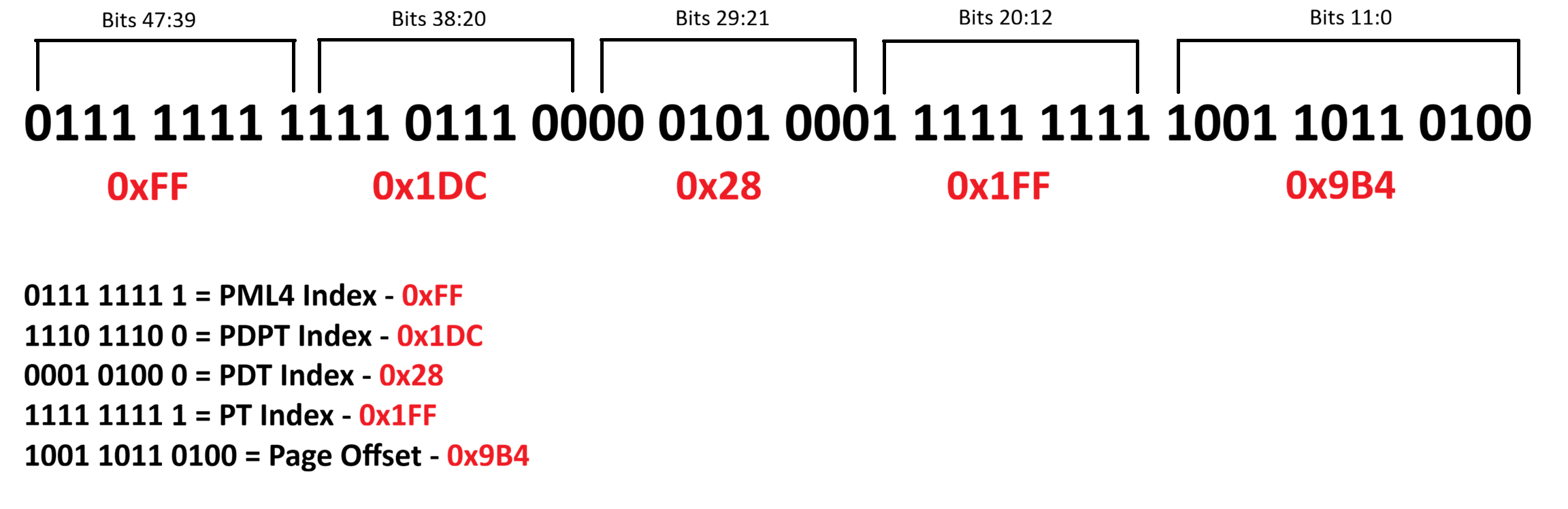
Following the table from earlier, let’s begin to break this down.
So we start by first taking the Page Map Level 4 (PML4) Index Bits
0111 1111 1 (47-39th bit)
Converting from binary to hexadecimal we get 0xFF or 255 in decimal. This is the index of the Page Map Level 4 Entry (PML4E).
Next we take the Page Directory Pointer Table (PDPT) Index Bits
1110 1110 0 (38-30th bit)
Again we convert the bits from binary to hexadecimal and we get 0x1DC or 476 in decimal. This is the index of the Page Directory Pointer Table Entry (PDPE).
Next we repeat the same process to calculate our Page Directory Table (PDT) index.
0001 0100 0 (29-21st bit)
We convert the bits from binary to hexadecimal and we get 0x028 or 40 in decimal. This is the index of the Page Directory Table Entry (PDPE).
Next we repeat the same process for the Page Table Entry (PTE).
1111 1111 1 (20-12th bit)
Converting these bits from binary to hexadecimal gives us 0x1FF or 511 in decimal. This is the index of the Page Table Entry (PTE).
Lastly, we need to calculate the page offset, these are bits 11:0.
1001 1011 0100 (11-0th bit)
We convert the bits into hexadecimal which is 0x9B4 or 2484 in decimal. This is the offset, the location difference between the start of the page and where the address’ instruction is located within the page.
| Table Index | Binary Representation | Table Entry Offset |
|---|---|---|
| Page Map Level 4 Entry | 0111 1111 1 | 0xFF |
| Page Directory Pointer Table Entry | 1110 1110 0 | 0x1DC |
| Page Directory Table Entry | 0001 0100 0 | 0x28 |
| Page Table Entry | 1111 1111 1 | 0x1FF |
| Page Offset | 1001 1011 0100 | 0x9B4 |
We’ve calculated our indicies from our virtual memory address!
In the next section, we’re going to cover how to use these indicies to manually traverse through the page tables to resolve a virtual address to it’s corresponding physical address.
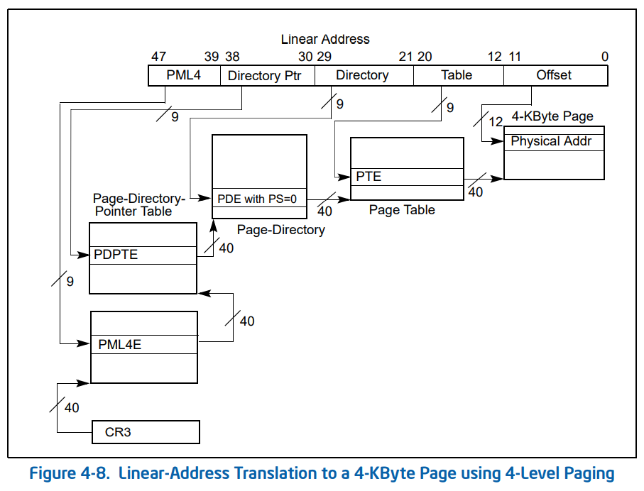
8. Page Table Translation Process
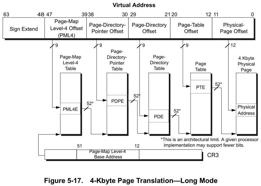
Don’t freak out just yet, the above diagram can be initially intimidating.
Using the example 64 bit virtual memory address used in the previous section, let’s perform a manual page table translation to better understand how this works.
First we must understand how we derive the location of each table. Each page table entry, points to the physical memory address of the base of the next table in the hierarchy. This is a crucial part to understanding how walking the page tables works.
- The Page Map Level 4 Entry (PML4E) points to the Page Directory Pointer Table (PDPT) Base.
- The Page Directory Pointer Entry (PDPE), points to the base of the Page Directory Table (PDT).
- The Page Directory Entry (PDE) points to the base of the Page Table (PT).
- The Page Table Entry (PTE) contains a Page Frame Number (PFN). This page frame number, tells us which physical page frame our virtual page is mapped too.
Now that we have calculated our indices in the previous section, we can use these to calculate the memory addresses for the necessary entries of each table.
Lets Begin
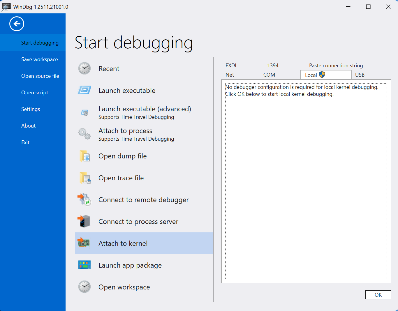
Let’s start by running WinDbg and attaching to the kernel locally.
I previously mentioned that the physical address of the first table within the hierarchy, is stored in the DirectoryTableBase value within the KPROCESS structure. This value is also stored within the CR3 register when using four level paging.
We can use the following WinDbg command to iterate all processes and output their DirectoryTableBase values.
!process 0 0
Find the process that contains the virtual address you’re trying to resolve.
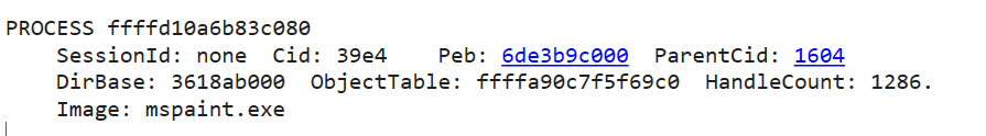
As you can see my virtual address that I’m trying to translate is within my mspaint.exe process.
We can see DirBase in the output, this is the DirectoryTableBase that stores the physical base address of the top most table in the page map.
So we begin by starting with the top most table in the page map, in our case Page Map Level 4 (PML4), as four level paging is enabled.
We have the physical base address of the PML4 (DirBase) from WinDbg, we begin here.
Page Map Level 4 Base
0x3618ab000
Page Map Level 4 Entry
We can calculate the memory address of our Page Map Level 4 Entry (PML4E) using the following formula.
PML4 Table Base Address + PML4E Byte Offset = Page Map Level 4 Entry (PML4E)
Just a quick note, if you’re using four level paging, or two/three level paging with PAE enabled, then each entry within the tables are 8 bytes each in size. If you’re using 32 bit and PAE is disabled, the table entries are 4 bytes in size.
As we’re using four level paging, we can multiply the page table index by 8, this will give us the byte offset, the distance in memory between the address of the base of the table and the table entry address.
The term ‘offset’ in this context refers to the distance between two locations. In our case, we will be referring to the distance between a tables base address and the table entry address.
So we take our PML4 index, which is 0xFF and multiply by 8 and we get 0x7F8. This is the distance in memory between the PML4 base address and the PML4 entry address.
0x3618ab000 + 0x7F8 = 0x3618AB7F8
So our PML4E address is 0x3618AB7F8.
Remember, the table entries are a pointer that points to the base address of the next table in the hierarchy.
So the value stored at this address, contains the physical base address for the next table in the structure. The next being the Page Directory Pointer Table (PDPT).
We can determine the value stored at the PML4E address by using the following command in WinDbg.
The ‘!’ prefix before the dq statement, tells WinDbg the address you’re parsing is a physical address.
!dq 0x3618AB7F8 L1
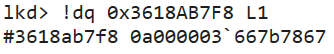
As you can see the output we receive is 0a000003`667b7867
To reiterate again, each table entry is a pointer to a value that contains the physical base address of the next table.
So the value stored at the PML4E address is 0a000003667b7867 which contains the Page Directory Pointer Table (PDPT) base address.
However in order to interpret this address correctly in this context, we need to quickly re-visit and talk about the structure of the page table entries.
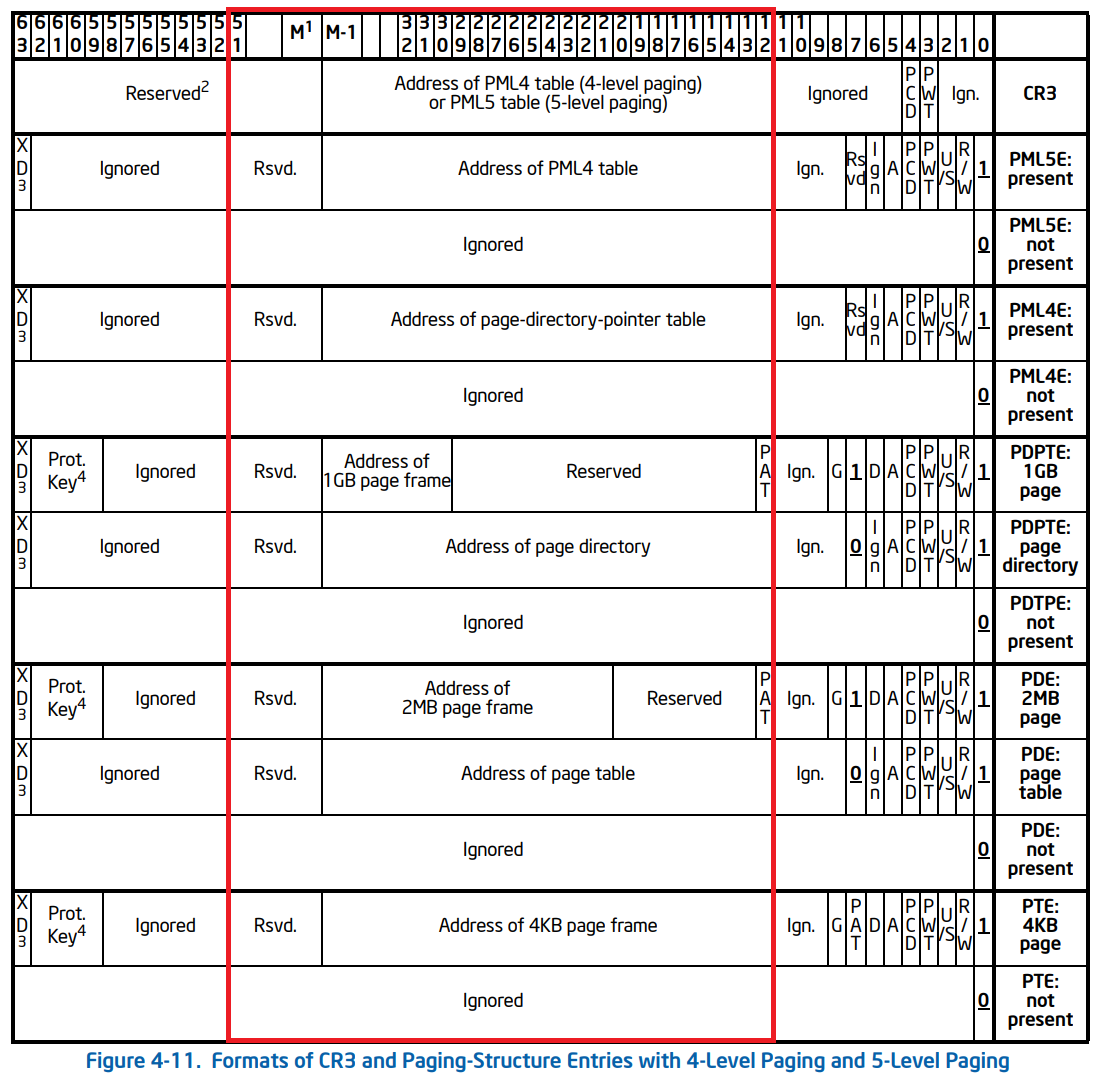
As you can see the bit range responsible for pointing to the physical address of the next table are uniform across the page table entry structures. The bit range (12:51) contains the physical address of the next table, which is what we’re after.
The other bits as you can see, are mostly encoded information such as flags. Those flags being responsible for information such as: Valid/Invalid status, Read/Write Permissions, Usermode/Kernelmode access, Accessed status, etc…
Using WinDbg, we can mask the address stored at the PML4 Entry using a bitwise and operation. This will zero/cleave the bits off that we don’t need and leave us with just the bits responsible for pointing to the address of the next table.
In WinDbg ? denotes the evaluation of an expression.
In WinDbg, use the following command to mask the bits. This will keep bits (12:51) that contain the address of the next table.
? (0a000003`667b7867 & 0xFFFFFFFFFF000)

Once you have masked the address and cleaved off the bits we don’t need, we are left with the actual physical base address of the next table, the PDPT!
Page Directory Pointer Table Base
0x3667b7000
Page Directory Pointer Entry
Again, we repeat the same process to calculate the memory address of the Page Directory Pointer Entry (PDPE).
From our virtual memory address, we get our PDPT index, multiply it by 8, as each entry within the table are 8 bytes.
This gives us the byte offset between the Page Directory Pointer Table (PDPT) base and the Page Directory Pointer Entry (PDPE).
From there, we simply add the table base with the table entry offset.
PDPT Base + PDPE Byte Offset = Page Directory Pointer Entry (PDPE)
0x3667b7000 + 0xEE0 = 0x3667B7EE0
So our Page Directory Pointer Entry (PDPE) address is 0x3667B7EE0
The value stored at the memory address of the Page Director Pointer Entry (PDPE), contains the physical base address of the Page Directory Table (PDT).
We can see the value stored at this address by using the !dq command again in WinDbg.
!dq 0x3667B7EE0 L1

As you can see the result is 00000003`667b8867
We again only want the bits of the address that are responsibly for pointing to the address of the next table bits (12:51). So as we did earlier, we can mask the address for bits (12:51) in WinDbg.
? (00000003`667b8867 & 0xFFFFFFFFFF000) 
The result after masking the address bits (12:51), we have the physical base address of the Page Directory Table (PDT)!
Page Directory Table Base
0x36c1b8000
Page Directory Entry
Let’s repeat this again to calculate our Page Directory Entry (PDE).
We take our Page Directory Table Index and multiply it by 8, as each entry in the table are 8 bytes in size. This provides us with the byte offset, the distance between the page directory table base and the page directory entry.
0x28 * 8 = 0x140
From there, we follow the same formula we have for the previous tables.
PDT Base + PDE Byte Offset = Page Directory Table Entry (PDE).
0x0x36c1b8000 + 0x140 = 0x36C1B8140
So our Page Directory Entry (PDE) physical address is 0x36C1B8140
The value stored at the memory address of the Page Directory Entry (PDE), contains the physical base address of the Page Table (PT).
For the thousandth time, we can use the !dq command again in WinDbg to find the value stored at the PDE address.
!dq 0x36C1B8140 L1 
As a result, we get 0x36c1b9867
Now again we only need the physical address of the next table, so lets mask the address for bits (12:51) in WinDbg.
? (0x36c1b9867 & 0xFFFFFFFFFF000)

As a result we get the base address of the next table in the hierarchy, the Page Table (PT) 0x36c1b9000.
Page Table Base
0x36c1b9000
Page Table Entry
Aaaaand for the last time, we follow the exact same procedure as the previous tables.
A page table entry (PTE) stores the page frame number of the physical page frame in which the virtual page is mapped too.
Let’s take our index 0x1FF and multiply it by 8, giving us our byte offset 0xFF8.
PT Base + PTE Byte Offset = Page Table Entry (PTE).
0x36c1b9000 + 0xFF8 = 0x36C1B9FF8.
So the physical address of our Page Table Entry (PTE) is 0x36C1B9FF8.
Let’s take a look at what value is stored at the PTE address.

The value stored at the PTE address is 0x34ea16025

After masking the bits (12:51) we get 0x34ea16000.
This is the physical base address of the page frame in which our virtual page is mapped too.
Translated Address
Finally! Now the final step in order to calculate the physical address.
We need to determine where exactly within the page the instruction lives.
We do this by adding the page offset with the page frame number, resulting in the exact physical location of our virtual address.
Physical Frame Base Address + Page Offset = Physical Address.
0x34ea16000 + 0x9B4 = 0x34EA169B4.
Virtual Address: 0x7FF7051FF9B4
Physical Address: 0x34EA169B4
Conclusion
Here’s a quick summary of the memory addresses for each table and their respective entries.
| Table Index | Physical Address |
|---|---|
| DirectoryTableBase | 0x3618ab000 |
| Page Map Level 4 | 0x3618ab000 |
| Page Map Level 4 Entry | 0x3618AB7F8 |
| Page Directory Pointer Table | 0x3667b7000 |
| Page Directory Pointer Entry | 0x3667B7EE0 |
| Page Directory Table | 0x36c1b8000 |
| Page Directory Entry | 0x36C1B8140 |
| Page Table | 0x36c1b9000 |
| Page Table Entry | 0x36C1B9FF8 |
| Physical Page Frame | 0x34ea16000 |
| Physical Address | 0x34EA169B4 |
Let’s check our calculations against WinDbg and see if there are any discrepencies.
We can use the following command in WinDbg to walk the page tables. !vtop DirBase VirtualAddress
!vtop 3618ab000 7FF7051FF9B4
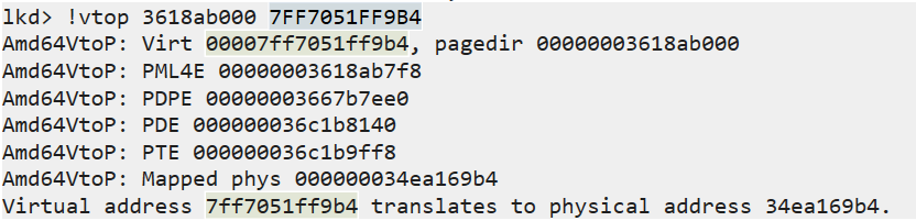
As you can see, the output shows the same addresses we calculated manually.
We’ve successfully traversed through the page tables, translating a virtual address to it’s corresponding physical memory address, where the instruction ACTUALLY lives in memory.
Think about it for a minute - your computer is capable of performing this lookup process billions of times per second.
It’s doing this at a speed that we can’t even fathom, all whilst we surf the internet, play games, scroll on our phones. Modern computers are powerful, we exist at an interesting time in history.
9. References
“Virtual Memory.” Wikipedia, 7 Feb. 2020, en.wikipedia.org/wiki/Virtual_memory.
Bell, John. “Operating Systems: Main Memory.” Uic.edu, 2019, www.cs.uic.edu/~jbell/CourseNotes/OperatingSystems/8_MainMemory.html.
Bell, John. “Operating Systems: Virtual Memory.” Uic.edu, 2019, www.cs.uic.edu/~jbell/CourseNotes/OperatingSystems/9_VirtualMemory.html.
Deland-Han. “Virtual Memory in 32-Bit Version of Windows - Windows Server.” Learn.microsoft.com, learn.microsoft.com/en-us/troubleshoot/windows-server/performance/ram-virtual-memory-pagefile-management.
33c0c3. “An Introduction to Physical Memory.” UnKnoWnCheaTs, 23 Nov. 2022, www.unknowncheats.me/forum/general-programming-and-reversing/523359-introduction-physical-memory.html.